
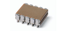
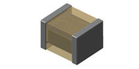
- InterdigitatedCap
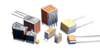
High Frequency Interdigitated Stacks
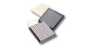
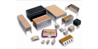
- MultilayerCeramicChips200x100
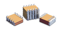
Multilayer Ceramic Chips
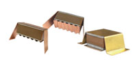
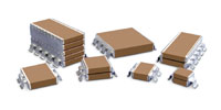
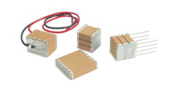
- PowerStacks
Power-Stack Capacitors
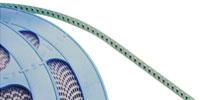
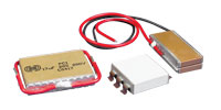
- TapeandReelfromMW
Buried Broadband
DC Blocking Capacitors - SLead Ceramic Capacitors
High Vibration "S" Leads
- Potted ceramic capacitors
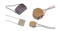
Encapsulated Products
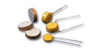
- RadialLeads200x100
High Voltage Disk
Ceramic Capacitors - Down Hole Oil & High Temperature Ceramic Capacitors
High Temperature Dielectrics
- UltraHighQPorcCap
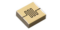
Ultra High Q Capacitors
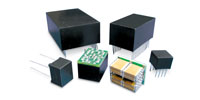
- SMPS-Stacks-small
SMPS Stacked Capacitors
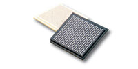
- WafflePacksFromMWBro
Buried Single Layer & Vertical Electrodes
- High Frequency High Power Ceramic Capacitors
High Frequency/High Power
- Custom Stacks and Custom Assembly
Custom Stacks
Custom Assembly - Custom Lead Ceramic Capacitors
Custom Leads
- Custom Shapes and sizes available
Custom Shapes & Sizes
- High Temp Ceramic Capacitors
High Temperature Ceramic Capacitors
- S-Lead Ceramic Capacitors
High Vibration Ceramic Capacitors
- Caps for EFI Detonators
Pulse Energy Capacitors
| Home | Contact Us | About | Sales Reps | Test Capabilities | Wright Capacitors |
|

- Presidio Components San Diego Plant
Presidio Components, Inc., San Diego, California
- Ceramic Capacitors for Space and Commumications
NASA-S-311-P-829 Specified Capacitors
- Capacitors for Space, Missile and Communications
Capacitors for Defense Applications
- High Temperature Avionics Capacitors
High Temperature Avionics
- RF and Cellular Communications capacitors
Fiber Optic Solutions
- Power and Embedded Industrial capacitors
High End Industrial Applications
- Electronic Warfare Systems Capacitors
Military Aerospace Applications
- High Temperature Down Hole Oil capacitors
High Temperature Down Hole Oil Applications
- Capacitors for IRED/Optical Systems and Radar
RF Power Solutions
- Capacitors Supplier for space programs
Space Applications
- RF and Cellular Capacitors
Microwave Communications
- Space Capacitors
Specialty Capacitors for the Mars Rovers
- Military and guidance system capacitors
Military Aerospace Applications
- Presidio Ceramic capacitors for Space, Missiles and Communications
Defense Applications
- NASA qualified capacitor manufacturer and military supplier
NASA-S-311-P-829 Specified Capacitors
- High Temp Caps for Oil and Gas Exploration
High Temp Caps for Oil and Gas Exploration
- Capacitors for Missile Guidance Systems
Capacitors for Missile Guidance Systems
- Pulse Energy Capacitors for EFI Detonators
Caps for EFI Detonators
|
MIL-PRF-55681 CDR Ceramic Chip Capacitors |
Size |
CDR01 | CDR02 | CDR03 | CDR04 | CDR05 | |||||||||
| L inch (mm) |
0.080 ± .015 (2.03 ± 0.38) |
0.180 ± .015 (4.57 ± 0.38) |
0.180 ± .015 (4.57 ± 0.38) |
0.180 ± .015 (4.57 ± 0.38) |
0.180 +.020/-.015 (4.57 +0.51/- 0.38) |
|||||||||
| W inch (mm) |
0.050 ± .015 (1.27 ± 0.38) |
0.050 ± .015 (1.27 ± 0.38) |
0.080 ± .015 (2.03 ± 0.38) |
0.125 ± .015 (3.18 ± 0.38) |
0.250 +.020/-.015 (6.35 +0.51/- 0.38) |
|||||||||
| T min. inch (mm) |
0.022 (0.56) | 0.022 (0.56) | 0.022 (0.56) | 0.022 (0.56) | 0.020 (0.51) | |||||||||
| T max. inch (mm) |
0.055 (1.40) | 0.055 (1.40) | 0.080 (2.03) | 0.080 (2.03) | 0.080 (2.03) | |||||||||
| M.B. inch (mm) |
0.020 ± .010 (0.51 ± 0.25) |
0.020 ± .010 (0.51 ± 0.25) |
0.020 ± .010 (0.51 ± 0.25) |
0.020 ± .010 (0.51 ± 0.25) |
0.020 ± .010 (0.51 ± 0.25) |
|||||||||
| Dielectric | BP | BX | BX | BP | BX | BP | BX | BP | BX | |||||
| WVDC | 100 | 100 | 50 | 100 | 50 | 100 | 100 | 50 | 100 | 100 | 50 | 100 | 100 | 50 |
| Capacitance in pF |
10 - 180 |
120 - 3300 |
3900 - 4700 |
3900 - 10000 |
12000 - 22000 |
330 - 1000 |
12000 - 33000 |
39000 - 68000 |
1200 - 3300 |
39000 - 56000 |
82000 - 180000 |
3900 - 5600 |
68000 - 150000 |
220000 - 330000 |
| Tolerance | J, K, M | K, M | J, K, M | J, K | K, M | J, K | K, M | |||||||
| Termination | M, S, U, W, Z | M, S, U, W, Z | M, S, U, W, Z | M, S, U, W, Z | M, S, U, W, Z | |||||||||
| Life Failure Rate |
M, P, R, S | M, P, R, S | M, P, R, S | M, P, R, S | M, P, R, S | |||||||||
| Designation | HR0805 | HR1805 | HR1808 | HR1812 | HR1825 | |||||||||
| Test or Qual Reference |
55681-659-85 | 55681-049-00 | 55681-660-85 | 55681-049-00 | 55681-049-00 | |||||||||
| Specification Sheet |
/1 | /1 | /1 | /1 | /2 | |||||||||
Size |
CDR06 | CDR11 | CDR12 | CDR13 | |||
| L inch (mm) |
0.225 ± .020 (7.52 ± 0.51) |
0.055 ± .015 (1.40 ± 0.38) |
0.055 ± .025 (1.40 ± 0.64) |
0.110 ± .020 (2.79 ± 0.51) |
|||
| W inch (mm) |
0.250 ± .020 (6.35 ± 0.51) |
0.055 ± .015 (1.40 ± 0.38) |
0.055 ± .015 (1.40 ± 0.38) |
0.110 ± .020 (2.79 ± 0.51) |
|||
| T min. inch (mm) |
0.020 (0.51) | 0.020 (0.51) | 0.020 (0.51) | 0.030 (0.76) | |||
| T max. inch (mm) |
0.080 (2.03) | 0.057 (1.45) | 0.057 (1.45) | 0.102 (2.59) | |||
| M.B. inch (mm) |
0.020 ± .010 (0.51 ± 0.25) |
0.010 -.005/+.010 (0.25 -0.13/+0.25) |
0.010 -.005/+.010 (0.25 -0.13/+0.25) |
0.015 ± .010 (0.38 ± 0.25) |
|||
| Dielectric | BP | BX | BG, BP | BP | BG | BP | BG, BP |
| WVDC | 100 | 50 | 150, 50 | 50 | 50 | 50 | 200, 500 |
| Capacitance in pF |
6800 - 10000 |
390000 - 470000 |
.1 - 100 |
110 - 1000 |
.1 - 100 |
.1 - 1000 |
.1 - 100 |
| Tolerance | J, K, M | B, C, D, F, G, J, K, M | B, C, D, F, G, J, K, M | B, C, D, F, G, J, K, M | |||
| Termination | M, S, U, W, Z | M, S, U, W, Z | M, S, U, W, Z | M, S, U, W, Z | |||
| Life Failure Rate |
M, P, R, S | M, P | M, P | M, P | |||
| Designation | HR2225 | HR0505 | HR0505 | HR1010 | |||
| Test or Qual Reference |
55681-049-00 | 55681-709-03 | 55681-709-03 | 55681-049-00 | |||
| Specification Sheet |
/3 | /4 | /4 | /4 | |||
| Size | CDR31 | CDR32 | CDR33 | CDR34 | CDR35 | |||||||||||||
| L inch (mm) |
0.078 ± .008 (2.00 ± 0.20) |
0.125 ± .008 (3.20 ± 0.20) |
0.125 ± .010 (3.20 ± 0.25) |
0.176 ± .010 (4.50 ± 0.25) |
0.176 ± .012 (4.50 ± 0.30) |
|||||||||||||
| W inch (mm) |
0.049 ± .008 (1.25 ± 0.20) |
0.062 ± .008 (1.60 ± 0.20) |
0.098 ± .010 (2.50 ± 0.25) |
0.125 ± .010 (3.20 ± 0.25) |
0.250 ± .012 (6.40 ± 0.30) |
|||||||||||||
| T max. inch (mm) |
0.051 ± .008 (1.30 ± 0.20) |
0.051 ± .008 (1.30 ± 0.20) |
0.059 ± .010 (1.50 ± 0.25) |
0.059 ± .010 (1.50 ± 0.25) |
0.059 ± .012 (1.50 ± 0.30) |
|||||||||||||
| M.B. inch (mm) |
0.020 ± .008 (0.51 ± 0.20) |
0.020 ± .008 (0.51 ± 0.20) |
0.020 ± .010 (0.51 ± 0.25) |
0.020 ± .010 (0.51 ± 0.25) |
0.020 ± .012 (0.51 ± 0.30) |
|||||||||||||
| Dielectric | BP | BX | BP | BX | BP | BX | BP | BX | BP | BX | ||||||||
| WVDC | 100 | 50 | 100 | 50 | 100 | 50 | 100 | 50 | 100 | 50 | 100 | 50 | 100 | 100 | 50 | 100 | 50 | 50 |
| Capacitance in pF |
1 - 470 |
510 - 680 |
470 - 4700 |
5600 - 18000 |
1 - 1000 |
1100 - 2200 |
4700 - 15000 |
18000 - 39000 |
1000 - 2200 |
2400 - 3300 |
15000 - 27000 |
39000 - 100000 |
2200 - 4700 |
27000 - 56000 |
100000 - 180000 |
4700 - 10000 |
11000 - 22000 |
180000 - 470000 |
| Tolerance | B, C, D, F, G, J, K, M | B, C, D, F, G, J, K, M | F, J, K, M | F, J, K | K, M | F, J, K | K, M | |||||||||||
| Termination | M, S, U, W, Z | M, S, U, W, Z | M, S, U, W, Z | M, S, U, W, Z | M, S, U, W, Z | |||||||||||||
| Life Failure Rate |
M, P, R, S | M, P, R, S | M, P, R, S | M, P, R, S | M, P, R, S | |||||||||||||
| Designation | HR0805 | HR1206 | HR1209 | HR1712 | HR1725 | |||||||||||||
| Test or Qual Reference |
55681-049-00 | 55681-049-00 | 55681-049-00 | 55681-049-00 | 55681-049-00 | |||||||||||||
| Specification Sheet |
/7 | /8 | /9 | /10 | /11 | |||||||||||||
| Consult factory for current qualification status. | ||||||||||||||||||||||||||||||||||||||||||||||||
MIL-PRF-123 Capacitor Dimensions |
||||||||||||||||||||||||||||||||||||||||||||||||
|
||||||||||||||||||||||||||||||||||||||||||||||||
| Home | Products | Implant Medical Applications |